
We would like to thank our loyal fellow members of the Nike Historical Society for your continued support over the years.
We will be closing the Society, including the store, as of March 31, 2024.
We have acquired a large repository of Nike technical information.
The web site will continue to be available.
It has been our pleasure to keep the legacy of the Nike missile's contribution of the successful conclusion to the Cold War.
the Board of Directors
Nike Historical Society
TAKEN FROM TM 9-1400-250-10/2
Section 1. FUNCTIONAL DESCRIPTION
29 (U). General
The guided missile launching set consists of the launchers, the controlling and indicating equipment, and the testing equipment required to prepare, monitor, test, and launch a Nike-Hercules or a Nike-Ajax guided missile.
30 (U). Launching Control
Under normal conditions, the operations leading to the launching of a guided missile are initiated and controlled from the batter control area. Under emergency conditions, the required information can be transmitted by voice communications from the battery control area to the launching set. Then the operation of the guided missile launching set is controlled locally from the launching control console in the trailer mounted launching control station or from the Hercules launching control-indicator in the launching section. The guided missile launching control officer who is in contact, by voice communications, with operating personnel in the battery control area and the launching sections.
31 (U). Safety Provisions
The control and firing circuits of the guided missile launching set are interlocked in a logical firing sequence. Interlocked circuits provide maximum safety to personnel and insure that prerequisite circuit functions in the firing sequence are completed before the subsequent circuit function is initiated.
32 (U). Indicators
Color-coded indicator lights at the launching control console, at the Hercules launching section control-indicator, and at the launcher control-indicator indicate the completion of all important circuit functions of the guided missile launching set. Illuminated green indicator lights indicate to the operator that the specific circuit function has been completed; illuminated amber or red indicator lights indicate that the specific circuit function has not been completed.
33. (U). Communications
The guided missile launching set is linked to the battery control area by a voice communications network. The guided missile launching set can also be linked to the battery control area by radio communications.
34. (U). Operating Power Sources
Both 60-cps and 400-cps electrical power is required for operation of the launching set. The 400-cps power is obtained by means of frequency converters that convert 60-cps power to 400-cps power. Under normal conditions, commercial 60-cps power is utilized; under emergency conditions, engine-driven generators supply the 60-cps power.
Section II. PHYSICAL ARRANGEMENTS
35 (u). General
The guided missile launching set is the equipment located in the launching area of the Nike-Hercules battery (fig. 8). The launching set described in the manual is emplaced as a fixed defense installation in the Continental United States (CONUS).
36 (U) Launching Area
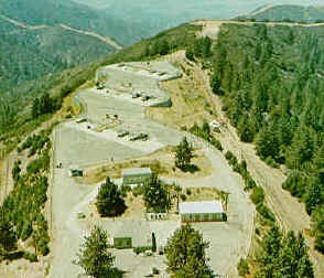
a. A typical launching area is shown in figure 30. The launching set in a typical launching area is normally composed of three launching sections and a trailer mounted launching control station. The launching set may contain a combination of Nike-Ajax and Nike-Hercules sections, as shown in figure 30, or Nike-Hercules sections only.
b. The launching are requires a rectangular are of approximately 43 acres. When terrain and real estate availability permit, the launching area is oriented with the launchers facing in the direction of the primary target line as shown in figure 30, and with the shorter sides of the rectangular are parallel to the primary target line. This arrangement is desirable by is not mandatory. The launching sections are located approximately 60 feet apart. The trailer mounted launching control station is located to the rear of the launching sections at a minimum distance of 800 feet from the nearest launcher.
37 (U). Nike-Hercules Launching Sections
Four configurations of the Nike-Hercules launching sections are used in fixed CONUS sites. The four configurations are designated CONUS B, CONUS C, CONUS C Modified, and CONUS D. The CONUS B, CONUS C, and CONUS C Modified sections are Nike-Ajax sections that have been converted to accommodate Nike-Hercules equipment. The CONUS D section is designed specifically for Nike-Hercules equipment. More than one configuration may be employed within the same launching set..
a. CONUS B Launching Section. Four Hercules monorail launchers are used in a CONUS B launching section. Elevator-mounted launcher No. 1 can be loaded in the underground storage chamber and then raised to the surface for firing. Satellite launchers No. 2, No. 3, and No. 4 are permanently emplaced on the surface. The four launchers are interconnected with loading racks. The loading racks permit moving missiles between launchers. A launcher control-indicator is emplaced on the surface near satellite launcher No.4. The underground part of the launching section is constructed of reinforced concrete and consists of the underground storage chamber, section control room, and elevator well. The underground equipment includes loading racks for missile storage, three launcher control-indicators and the section control equipment. The section control equipment is composed of the Hercules launching section control-indicator and the Hercules section simulator group. Stairways, escape hatches, and blast proof doors are also provided. The launching section can accommodate seven ready Nike-Hercules missiles or ten ready Nike-Ajax missiles.
b. CONUS C Launching Section. A CONUS C Launching section is generally similar to the CONUS B section described in a above except for the following differences:
(1) Only three launchers are provided. An adapter rack is mounted on the elevator in place of elevator mounted launcher No. 1.
(2) Only two launcher control-indicators are required underground.
(3) The launching section can accommodate only six ready Nike-Hercules or Nike-Ajax missiles.
c. CONUS C Modified Launching Section. A CONUS C Modified launching section is generally similar to the CONUS B section is described in a above except for the following differences:
(1) An adapter rack is mounted on the elevator in place of elevator-mounted launcher No. 1.
(2) Four Hercules monorail launchers are permanently emplaced on the surface. The four launchers may be arranged with two to each side of the elevator, or with three on one side and one on the opposite side.
(3) Two launcher control-indicators are on the surface and two are underground.
(4) The launching section can accommodate only six ready Nike-Hercules or Nike-Ajax missiles.
d. CONUS D Modified Launching Section. A CONUS D launching section is generally similar to the CONUS B section described in a above except that the underground storage chamber contains an additional storage room and a fan room. A 400-cps frequency converter is located in the fan room.
Section III. EQUIPMENT DESCRIPTION
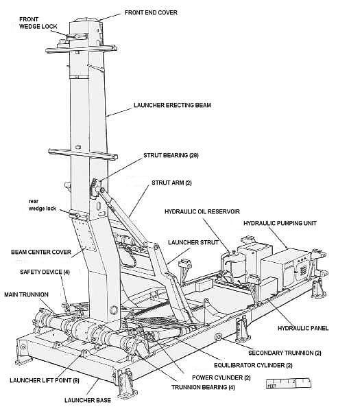
38 (U). Hercules Monorail Launcher
Note. The key numbers shown in parentheses in a and b below refer to figure 32.
a. The Hercules monorail launcher functions as a firing platform for both Nike-Hercules and Nike-Ajax missiles. The four Hercules monorail launchers (1,7,8, and 9) in a CONUS B launching section are identical except in emplacement. Launcher No. 1 (9) is elevator mounted; the satellite launchers (1,7, and 8) are emplaced on concrete aprons (5) on the surface. Emplacement of launchers in CONUS C, CONUS C Modified, and CONUS D sections is similar except for the differences outlined in paragraph 37.
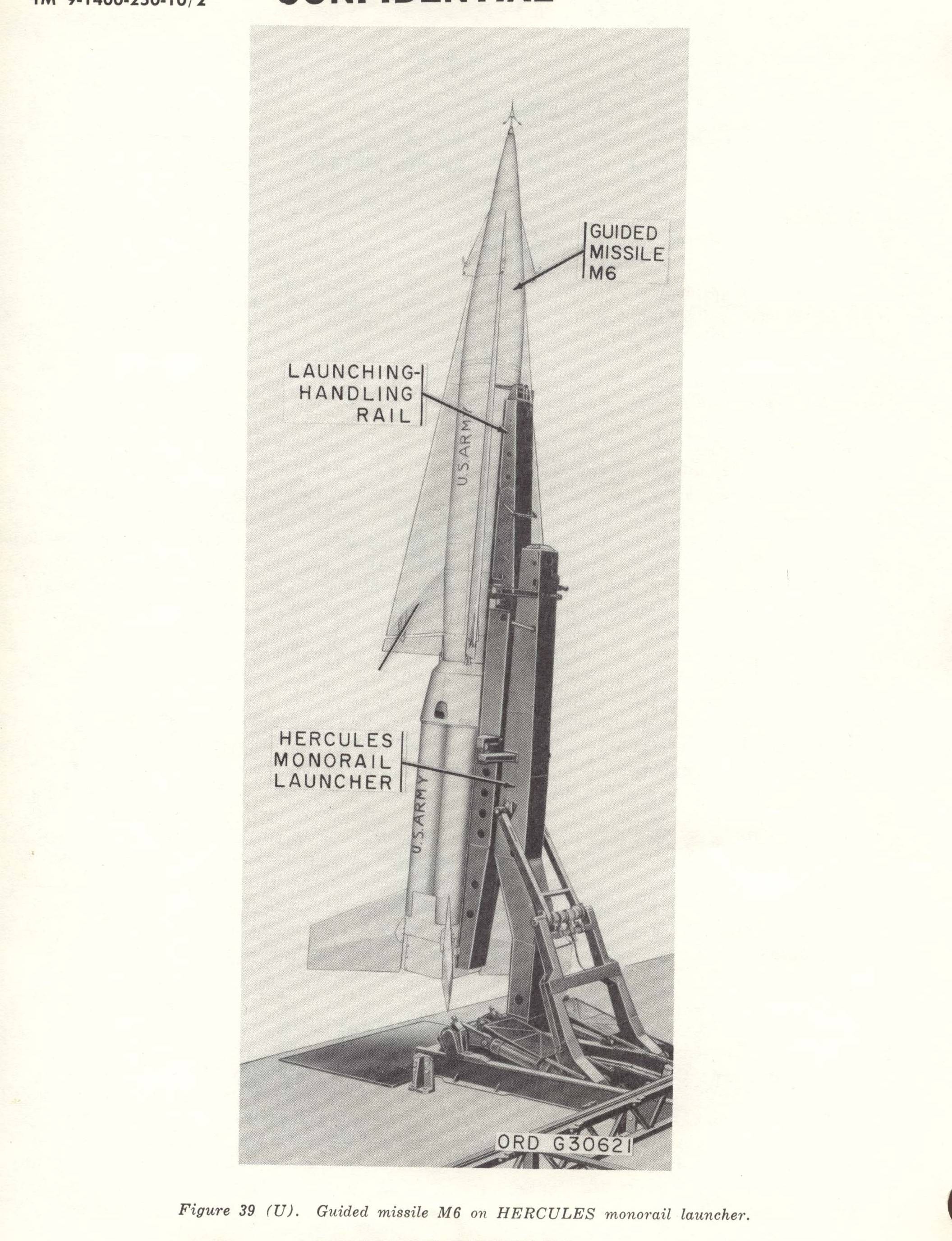
b. The Hercules monorail launcher is of box type welded steel construction and is approximately 23 feet long and 8 feet wide with an overall height of 31 1/2 inches. The launcher erecting beam (2) supports the launching-handling rail (3) and the missile. The erecting beam is erected and lower by means of a hydraulic system and is set for an erected angle of elevation of either 85 degrees, 87 1/2 degrees, or 90 degrees. The 87 1/2 degree angle is most commonly used.
39 (U). Launching-Handling Rail
a. The launching-handling rail (3, fig. 33) supports and guides the missile on the launcher during the fraction of a second required for the missile to become airborne, thereby assuring that the missile is launched at the correct angle. The rail also provides a means of moving the missile along the load racks.
b. The launching-handling rail (fig. 33) is approximately 26 1/2 feet long and 14 1/2 inches in height with an overall width of 40 inches at the outriggers. Hydraulic wedgelocks on the launcher erecting beam lock the locking lugs of the rail in position and secure the rail to the beam. The two stop bolts at the rear of the rail are used to adjust the position and secure the rail to the beam. The two stop bolts at the rear of the rail are used to adjust the position of the missile and to prevent the missile from sliding off the erected rail. The rail release, at the forward end of the rail, supports the forward end of the missile. At launch, the forward motion of the missile releases the rail release. The electrical breakaway shears an umbilical cable assembly from the missile at launch, thereby breaking the electrical connections between the missile and the launcher. The positioning handle and the inching hand wheel provide the means for releasing the rail and moving it along the loading racks. An electrical system in the rail provides the connections for testing and firing the missile.
40 (U). Launcher Control-Indicator
The launcher control-indicator (fig. 34) provides controls and indicators for testing and monitoring of missiles on the launchers and on loading racks, and provides local control of the launchers. One launcher control-indicator (LCI) is associated with each of the four Hercules monorail launchers. Each LCI is connected by cables to the Hercules launching section control-indicator in the section control room and to a launcher. The three LCI's located underground are also connected by cables to missile test stations on the loading racks. The underground LCI's control launchers No. 1, No. 2 and No. 3, and nine test stations. The LCI located on the surface controls launcher No. 4 but has no associated test stations.
41 (U). Hercules Launching Section Selector
The Hercules launching section selector (fig. 35) is installed in the section control room. The selector consists of the Hercules launching section control-indicator (1, fig. 35) and the Hercules section simulator group (2, fig. 35).
a. Hercules Launching Section Control-Indicator. The Hercules launching section control-indicator (1, fig. 35) is connected by cables to each launcher control-indicator in the launching section and to the trailer mounted launching control station. A control panel on the control-indicator contains controls and indicators required to prepare the missile for firing. A manual orders panel on the control-indicator is provided for emergency use when cables are disrupted between the launching area and the battery control area. The manual orders panel enables the operator at the launching section to complete the firing circuit.
b. Hercules Section Simulator Group. The Hercules section simulator group (2, fig. 35) is connected by cables to the Hercules launching section control-indicator, to each launcher, and to the launching section power source. The simulator group contains the electronic components required for presenting the roll amount gyro in the missile prior to launch.
42 (U). Trailer Mounted Launching Control Station
Note. The key letters shown in parentheses in paragraph 42 refer to figure 36.
The trailer mounted launching control station (fig. 36) contains the launching control group which consists of the launching console (3), the intercommunication cabinet station (4), the flight simulator group (2), the radar target simulator (1), and associated equipment required for tactical control of the launching area.
a. Launching Control Console. The launching control console (3) is located near the forward end of the trailer mounted launching control station. The launching control console (fig. 37) contains the controls and indicators required for tactical operation of the launching area and for coordination of operations between the battery control area and the launching area. The controls and indicators on the console provide the console operator with the information regarding the equipment status, the missile and mission designation, and the preparedness of each launching section. The console operator monitors the missile preparedness information from each section and selects the section to fire as directed by a launching control officer who is stationed at the launching control officer's desk (5) across from the console.
b. Intercommunication Cabinet Station. The intercommunication cabinet station (4) is located against the curbside wall of the trailer mounted launching control station. The intercommunication cabinet station contains equipment which provides two-way communication between all system telephone locations.
c. Flight Simulator Group. The flight simulator group (2), during operation, is hoisted to the top of a 30-foot mast attached to the front roadside corner of the trailer mounted launching control station. The simulator group simulates a missile for the missile tracking radar system prior to designation of a missile and between firing of missiles.
d. Radar Target Simulator. The radar target simulator (1) is mounted on top of the flight simulator group (2) and is used as a radar target for periodic checks of the target tracking radar system.
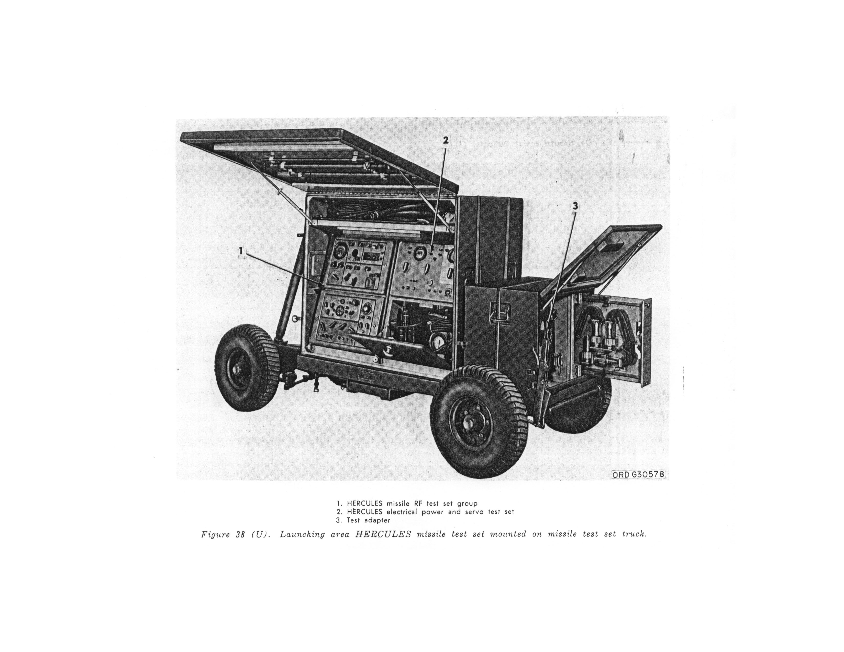
43 (U). Launching Area Hercules Missile Test Set
The launching area Hercules missile test set (fig. 38) includes the Hercules missile RF test set group (1, fig. 38), the Hercules missile RF test set group (1, fig. 38), the Hercules electrical power and servo test set (2, fig. 38) and test adapter (3, fig. 38). The equipment is used to perform operational checks on the missile guidance set of the Nike-Hercules missile and on the flight simulator group (2, fig. 36). The launching area Hercules missile test set is normally mounted on the missile test set truck, as shown in figure 38.
43.1 (U). Fault Locating Indicator
The fault locating indicator (fig. 38.1) and its associated equipment are used to locate faulty modules in guidance set transponder-control groups (mushroom only). These transponder-control groups will have been checked previously by the Nike-Hercules missile RF test set group and the Nike-Hercules missile electrical test set group and found to be faulty.
The last image (on the right) can be enlarged to examine details.