ASSEMBLY AND SERVICE AREA EQUIPMENT
THE FOLLOWING WAS TAKEN FROM TM 9-1400-250-10/2
Section 1. OVERALL FUNCTION
52 (U). Scope
This section explains the overall function of the assembly and service area and outlines the normal procedures in the handling of Nike-Hercules and Nike-Ajax missiles, from uncrating of the missile components to delivery of the missiles to the launching area.
53 (U). Assembly Area
a. The major components of the Nike-Hercules missile (guided missile M-6) are received in the assembly area (fig. 45) in shipping containers. The forward body section (fig. 40) and the rear body section are received in the same pressurized metal container. The warhead body section is received in a separate pressurized metal container. The main fins and elevons, the rocket motor cluster fins and accessories, the rocket motor cluster (less fins), and missile rocket motor M30 (4, fig. 41) are received in individual wooden containers. The rocket motor igniters M24A1, missile rocker motor initiators, missile batteries, and other small components are received in individual cartons or cans.
b. The rear body section (fig. 40) and the forward body section of guided missile M-6 are uncrated, and the rear main fins and elevons are uncrated and installed on the rear body section. The forward body section is temporarily installed on the rear body section, the accessory power supply (5 fig. 41) or hydraulic pumping unit serviced, and functional tests are performed on the missile electrical, guidance, and hydraulic systems. At completion of these tests, the accessory power supply of hydraulic pumping unit is again serviced and the missile is taken to the service area (fig. 45) for installation of the missile rocket motor M30 (4, fig. 41) and the warhead body section (fig,. 40). The warhead body section, rocker motor cluster, missile rocket motor M30, and associated components are taken to the service area and are not uncrated until they are ready to be assembled or joined to the missile.
c. The missile body of the Nike-Ajax missile (guided missile M6) is received in the assembly area completely assembled except for the installation of the warhead and fins. After uncrating, the fins are attached and functional tests are performed. The missile body is then transported to the service area for warhead installation and propellant fueling.
54 (U). Service Area
a. The warhead body section (fig. 40). rocket motor cluster, and missile rocket motor M30 (4, fig. 41) of guided missile M6 are uncrated in the service area (fig. 45). The rocket motor cluster is assembled on the rock motor cluster truck (fig. 46) with the exception of the two lower rocket motor cluster fins which are stored in the lower part of the truck for assembly on the cluster after it is transported to the launching area. A continuity test of the rocket motor igniters M24A1 is performed prior to installation. After this test, the rocket motor cluster is transported to the launching area either on the rocket motor cluster truck or on the missile body or rocket motor cluster transported adapter (fig. 46) mounted on the missile flat-bed trailer M261A1 (fig. 47). At the launching section, the rocket motor cluster is is removed from the truck or adapter with a hoisting device and the cluster is secured to a launching-handling rail (fig. 38).
b. The forward body section (fig. 40) is removed from the rear body section to permit installation of the missile rocket motor M30 (4, fig. 41) and the warhead body section (fig. 40). After the motor and warhead body section are installed, the forward body section is installed, and the missile body is transported to the launching area either on the Hercules missile body truck (fig. 46) or on the missile body or rocket motor cluster transporter adapter mounted on the missile flat bed trailer M261A1 (fig. 47). At the launching section, the missile body is removed from the missile truck or transporter adapter with the Hercules missile body hoist beam (fig. 50) attached to a hoisting device. The missile body is then joined to the rocket-motor cluster and secured to the launching-handling rail. After the missile body is joined to the rocket motor cluster, the lower rocket motor cluster fins, rocket motor igniters M24A1, and the safety arming devices M30A1 are installed.
c. The booster rocket motor for the Nike-Ajax missile (guided missile M1) is attached to a launching-handling rail on the missile flat bed trailer M261A1, and the missile body is joined to the rocket motor. A continuity check of the propulsion system is performed, the missile is fueled, the warheads are installed, and the missile is transported to the launching area where it is transferred from the missile flat bed trailer M261A1 to the loading racks at the launching section. There the lower booster fins, safety and arming devices, and nose closure fitting are installed and starting mixture is added.
Section II EQUIPMENT
55. (U). Scope
This section describes briefly the function of the handling and test equipment used primarily in the assembly and service area to uncrate, assemble, and test guided missile M-6.
56 (U) Handling Equipment
a. Hercules Missile Body Truck. The Hercules missile body truck (fig. 46), in conjunction with the Hercules handling ring segments (fig. 50), is used to support the rear body section (fig. 40) after its removal from the shipping container and during assembly and testing. The truck can be used to transport the rear body section from the assembly area to the service area and to transport the missile body from the service area to the launching area.
b. Forward Body Section Truck. The forward body section truck (fig. 46) is used to hold the forward body section (fig. 40) during the assembly of the missile.
c. Rocket Motor Cluster Truck. The rocket motor cluster truck (fig. 46) is used for assembly of the rocket motor cluster (fig. 40) and can be used to transport the cluster form the service area to the launching area. It can also be used to transport a launching-handling rail (fig. 33), a missile body or rocket motor cluster transporter adapter (fig. 46), or a missile body (fig. 40).
d. Missile Body or Rocket Motor Cluster Transporter Adapter. The missile body or rocker motor cluster transporter adapter (fig. 46) is used to support the missile body (fig. 40) or the rocker motor cluster while transporting either unit from the service area to the launching area.
e. Missile Flat Bed Trailer M261A1. Missile flat bed trailer M261A1 (fig. 47) is used in conjunction with the missile body or rocket motor cluster transporter adapter (fig. 46) to transport a missile body (fig. 40) or rocket motor cluster from the service area to the launching area.
f. Trailer Mounted Power Driven Reciprocating Compressor. The trailer mounted power driven reciprocating compressor (fig. 47) is used to provide clean dry air for servicing the accessory power supply (5, fig. 41) or the hydraulic pumping unit.
g. APS Filler and Service Equipment. The APS filler and service equipment (fig. 47) includes pressure tanks of ethylene oxide and nitrogen and the necessary valves and hoses for servicing the accessory power supply (5, fig. 41).
h. Handling Rack. The handling rack (fig. 47) is used to store a missile body (fig. 40) or a rocket motor cluster when either is mounted on a missile body or rocket motor cluster adapter (fig. 46). The handling rack may also be used to store the transporter adapter when the adapter is not in use.
i. Battery Charging Rack MT-1498/G. Battery charging rack MT-1498/G (fig. 48) is used to support and monitor missile batteries while they are being charged.
Note. Battery charging is required only on the chargeable storage batteries used in missile prior to serial number 13684. Missiles 13684 and subsequent use squib batteries that do not require charging.
j. Portable Hoisting Unit. The portable hoisting unit (fig. 49) is used with appropriate hoist beams to hoist the position missile components during assembly and joining operations.
k. Rocker Motor Cluster Hoisting Beam. The rocket motor cluster hoisting beam (fig. 50) is used to lift the rocket motor cluster (fig. 40) from the rocket motor cluster truck (fig. 46) to the missile flat bed trailer M261A1 (fig. 47) ore the launching-handling rail (fig. 33).
m. Rear Body Section Hoist Beam. The rear body section hoist beam (fig. 50) is used for transferring the rear body section (fig. 40) from the shipping container to the Hercules missile body truck (fig. 46).
n. Warhead Body Section Hoist Beam. The warhead body section hoist beam (fig. 50) is used to support and position the warhead body section (fig. 40) during installation of the warhead body section to the missile body.
o. Missile Rocket Motor Hoist Beam. The missile rocket motor hoist beam (fig. 50) is used to remove missile rocket motor M30 (4, fig. 41) from the shipping container and to support the motor while it is being installed in the missile body.
p. Ajax Rocket Motor Hoist Beam. The Ajax rocket motor hoist beam (fig. 50) is used to support rocket motor M5E1 (fig. 40) during assembly of the rocket motor cluster.
q. Hercules Handling Ring Segment. Four Hercules handling ring segments (fig. 50) are assembled to the rear body section (fig. 40) before the rear body section is placed on the Hercules missile body truck (fig. 46). The ring formed by the four segments rides on rollers at one end of the truck, permitting rotation of the ready body section for installation of the rear main fins and for other assembly and maintenance operations.
r. Power Supply Truck. The power supply truck (fig. 51) is used to provide electrical power for operating the hydraulic pumping unit during air and oil servicing and missile electrical checkout.
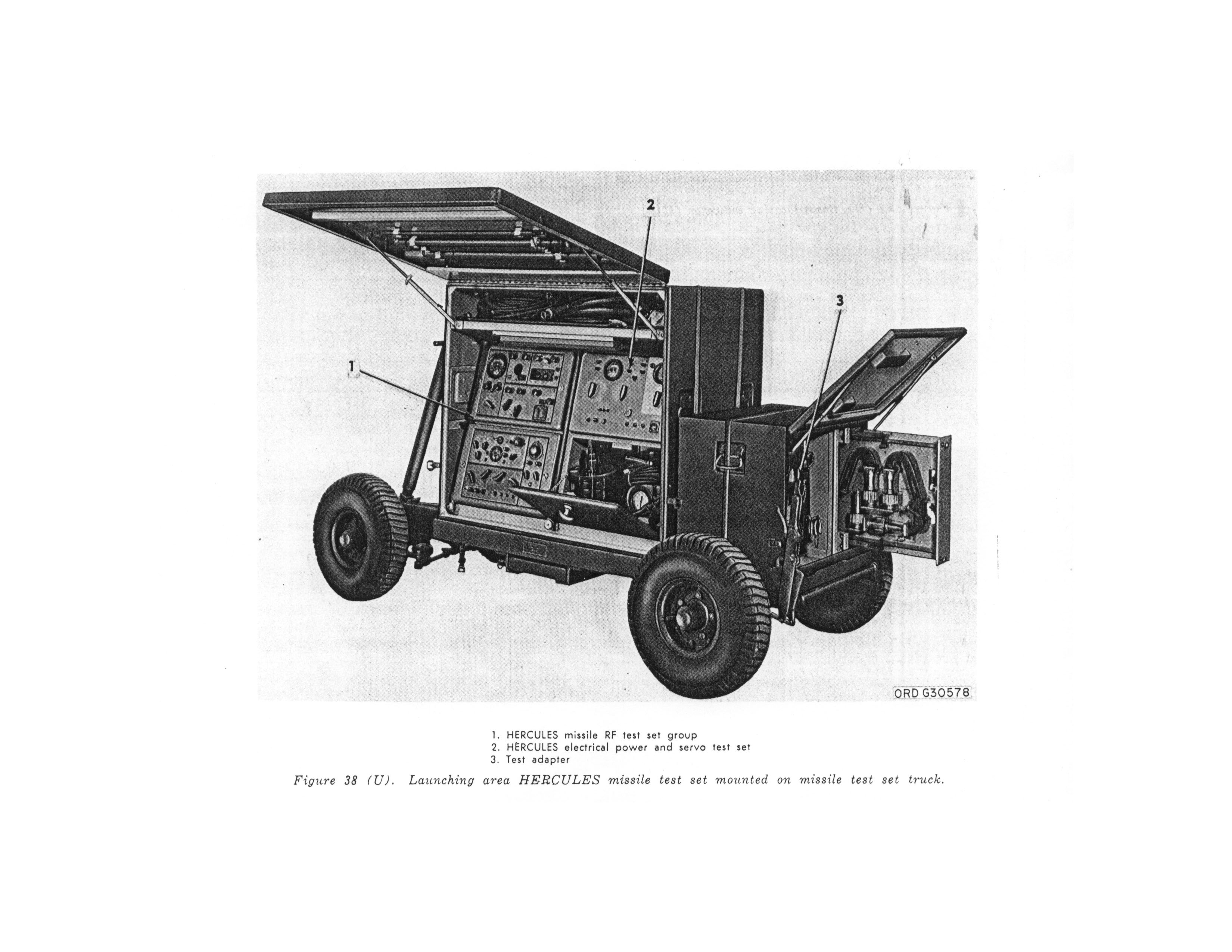
57 (U). Assembly Area Hercules Missile Test Set
The assembly area Hercules missile test set (fig. 52) includes the Hercules missile RF test set group (1, fig. 52), the Hercules missile electrical test set group (a, fig. 52), and the test adapter (3, fig. 52). The Hercules missile RF test set group generates rf signals that simulate guidance commands to test the response of the missile guidance set and hydraulic system. The rf signals are coupled to the missile antennas by means of the test adapter and waveguides. The Hercules missile RF test set group also provides facilities for testing the servo systems and power supplies in the missile. The Hercules missile electrical test set group is used during servicing and hot run of the accessory power supply and, in conjunction with the Hercules missile RF test set group, during the missile electrical checkout.

 *
*
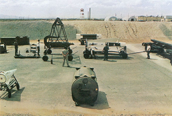
*Photo courtesy of NPS GGNRA Ezio Nurisio Nike Collection
The Nike-Hercules missile was originally designated as Guided Missile M-6.